使用交换机

理论基础

  1. 交换机是构建局域网的基础设备。交换机工作在数据链路层,又称为二层交换机,其功能是基于MAC地址进行数据帧的转发。交换机的每个接口都可以直接连接单台主机或另一台交换机,并以全双工方式巩固工作。交换机有一条高宽带的背部总线和内部交换矩阵。同时还有一个MAC地址与接口之间的映射表,即MAC地址表。当交换机接收到一个数据帧以后,会查看该帧首部的MAC地址,并依据MAC地址表,将该帧从对应的目的接口转发出去。
  2. 交换机的转发过程
    1. 接收到数据帧,提取MAC信息并与现有MAC地址表对比,若存在则更新MAC地址表生存期限
    2. 判断该数据帧的目的MAC是广播帧,还是单播帧
    3. 存在映射则进行单播,否则进行广播
    4. 有回复信息,则添加到MAC地址映射表
  3. 生成树协议STP
  4. 链路聚合
  5. 交换机命令行
    1. 用户视图
    2. 系统视图
    3. 业务视图

基本命令

1
2
3
4
5
6
7
8
9
10
11
12
13
14
15
16
17
18
19
20
21
22
23
24
25
26
27
28
29
30
31
32
33
34
35
36
37
38
39
40
41
42
43
44
45
46
47
48
49
50
51
52
53
54
55
56
57
58
59
60
61
62
63
64
65
66
67
68
69
70
71
72
73
74
75
76
77
78
79
80
81
82
83
84
85
86
87
88
89
90
91
92
93
94
95
96
97
98
99
100
101
102
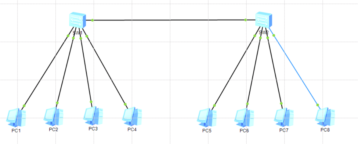
# 默认视图
<Huawei>
# 进入系统视图
<Huawei>system-view
Enter system view, return user view with Ctrl+Z.
[Huawei]
# 关闭信息中心
[Huawei]undo info-center enable
Info: Information center is disabled.
# 更改设备名称
[Huawei]sysname SW-1
# 显示当前配置
[SW-1]display current-configuration
#
sysname SW-1
#
undo info-center enable
#
cluster enable
ntdp enable
ndp enable
# 查看VLAN信息
[SW-1]display vlan
The total number of vlans is : 1
--------------------------------------------------------------------------------
U: Up; D: Down; TG: Tagged; UT: Untagged;
MP: Vlan-mapping; ST: Vlan-stacking;
#: ProtocolTransparent-vlan; *: Management-vlan;
--------------------------------------------------------------------------------

VID Type Ports
--------------------------------------------------------------------------------
1 common UT:Eth0/0/1(D) Eth0/0/2(D) Eth0/0/3(D) Eth0/0/4(D)
Eth0/0/5(D) Eth0/0/6(D) Eth0/0/7(D) Eth0/0/8(D)
Eth0/0/9(D) Eth0/0/10(D) Eth0/0/11(D) Eth0/0/12(D)
Eth0/0/13(D) Eth0/0/14(D) Eth0/0/15(D) Eth0/0/16(D)
Eth0/0/17(D) Eth0/0/18(D) Eth0/0/19(D) Eth0/0/20(D)
Eth0/0/21(D) Eth0/0/22(D) GE0/0/1(D) GE0/0/2(D)

VID Status Property MAC-LRN Statistics Description
--------------------------------------------------------------------------------
1 enable default enable disable VLAN 0001
# 查看接口信息
[SW-1]display interface Ethernet 0/0/1
Ethernet0/0/1 current state : DOWN
Line protocol current state : DOWN
Description:
Switch Port, PVID : 1, TPID : 8100(Hex), The Maximum Frame Length is 9216
IP Sending Frames' Format is PKTFMT_ETHNT_2, Hardware address is 4c1f-cca6-5838
Last physical up time : -
Last physical down time : 2025-03-03 17:29:10 UTC-08:00
Current system time: 2025-03-03 17:35:14-08:00
Hardware address is 4c1f-cca6-5838
Last 300 seconds input rate 0 bytes/sec, 0 packets/sec
Last 300 seconds output rate 0 bytes/sec, 0 packets/sec
Input: 0 bytes, 0 packets
Output: 0 bytes, 0 packets
Input:
Unicast: 0 packets, Multicast: 0 packets
Broadcast: 0 packets
Output:
Unicast: 0 packets, Multicast: 0 packets
Broadcast: 0 packets
Input bandwidth utilization : 0%
Output bandwidth utilization : 0%
# 查看接口配置,进入e0/0/1接口并显示
[SW-1]interface Ethernet 0/0/1
[SW-1-Ethernet0/0/1]display this
#
interface Ethernet0/0/1
#
return
# 退出接口视图
[SW-1-Ethernet0/0/1]quit
# 退出系统视图
[SW-1]quit
# 保存当前配置
<SW-1>save
The current configuration will be written to the device.
Are you sure to continue?[Y/N]y
Info: Please input the file name ( *.cfg, *.zip ) [vrpcfg.zip]:
Now saving the current configuration to the slot 0.
Save the configuration successfully.
# 重启交换机
<SW-1>reboot
Info: The system is now comparing the configuration, please wait.
Info: If want to reboot with saving diagnostic information, input 'N' and then execute 'reboot save diagnostic-information'.
System will reboot! Continue?[Y/N]:Y
# 重置交换机
<SW-1>reset saved-configuration
Warning: The action will delete the saved configuration in the device.
The configuration will be erased to reconfigure. Continue? [Y/N]:Y
Warning: Now clearing the configuration in the device.
Info: Succeeded in clearing the configuration in the device.
# 重启交换机方可生效,不再保存配置
<SW-1>reboot
Info: The system is now comparing the configuration, please wait.
Warning: All the configuration will be saved to the configuration file for the next startup:, Continue?[Y/N]:n
Info: If want to reboot with saving diagnostic information, input 'N' and then execute 'reboot save diagnostic-information'.
System will reboot! Continue?[Y/N]:y
<SW-1>
<Huawei>

简单组网

拓扑设置

交换机规划

序号 设备名称 接口 接口类型 对接设备/端口
1 SW-1 Ethernet 0/0/1 默认 PC1
2 SW-1 Ethernet 0/0/2 默认 PC2
3 SW-1 Ethernet 0/0/3 默认 PC3
4 SW-1 Ethernet 0/0/4 默认 PC4
5 SW-2 Ethernet 0/0/1 默认 PC5
6 SW-2 Ethernet 0/0/2 默认 PC6
7 SW-2 Ethernet 0/0/3 默认 PC7
8 SW-2 Ethernet 0/0/4 默认 PC8

主机IP地址规划表

序号 设备 IP地址/子网掩码 默认网关 接入交换机
1 PC1 192.168.24.11/24 192.168.24.2 SW-1
2 PC2 192.168.24.12/24 192.168.24.2 SW-1
3 PC3 192.168.24.13/24 192.168.24.2 SW-1
4 PC4 192.168.24.14/24 192.168.24.2 SW-1
5 PC1 192.168.24.15/24 192.168.24.2 SW-2
6 PC2 192.168.24.16/24 192.168.24.2 SW-2
7 PC3 192.168.24.17/24 192.168.24.2 SW-2
8 PC4 192.168.24.18/24 192.168.24.2 SW-2

配置启动网络

1
2
3
4
5
6
7
8
9
10
11
12
13
14
15
16
17
18
19
20
21
22
23
24
25
26
27
28
29
30
31
32
33
34
35
36
37
38
39
40
41
42
# 配置八台PC主机名和IP地址
# 在PC主机上分别进行ping操作
# 配置交换机并查看mac映射表
<Huawei>system-view
[Huawei]undo info-center enable
[Huawei]sysname SW-1
[SW-1]display mac-address
MAC address table of slot 0:
-------------------------------------------------------------------------------
MAC Address VLAN/ PEVLAN CEVLAN Port Type LSP/LSR-ID
VSI/SI MAC-Tunnel
-------------------------------------------------------------------------------
5489-982e-51fd 1 - - Eth0/0/1 dynamic 0/-
5489-9831-6fa5 1 - - Eth0/0/2 dynamic 0/-
5489-98d7-765d 1 - - Eth0/0/4 dynamic 0/-
5489-98bb-7c89 1 - - Eth0/0/3 dynamic 0/-
5489-9845-4413 1 - - GE0/0/1 dynamic 0/-
5489-98c8-48e9 1 - - GE0/0/1 dynamic 0/-
5489-984b-4cc0 1 - - GE0/0/1 dynamic 0/-
5489-9835-1bd7 1 - - GE0/0/1 dynamic 0/-
-------------------------------------------------------------------------------
Total matching items on slot 0 displayed = 8
# 查看第二台交换机的MAC地址表
<Huawei>system-view
[Huawei]undo info-center enable
[Huawei]sysname SW-2
[SW-2]display mac-address
MAC address table of slot 0:
-------------------------------------------------------------------------------
MAC Address VLAN/ PEVLAN CEVLAN Port Type LSP/LSR-ID
VSI/SI MAC-Tunnel
-------------------------------------------------------------------------------
5489-982e-51fd 1 - - GE0/0/1 dynamic 0/-
5489-98bb-7c89 1 - - GE0/0/1 dynamic 0/-
5489-98d7-765d 1 - - GE0/0/1 dynamic 0/-
5489-9831-6fa5 1 - - GE0/0/1 dynamic 0/-
5489-9845-4413 1 - - Eth0/0/1 dynamic 0/-
5489-98c8-48e9 1 - - Eth0/0/2 dynamic 0/-
5489-984b-4cc0 1 - - Eth0/0/3 dynamic 0/-
5489-9835-1bd7 1 - - Eth0/0/4 dynamic 0/-
-------------------------------------------------------------------------------
Total matching items on slot 0 displayed = 8

接 口管理

1
2
3
4
5
6
7
8
9
10
11
12
13
14
15
16
17
18
19
20
21
22
23
24
25
26
27
28
29
30
31
32
33
34
35
36
37
38
39
40
41
42
43
44
45
46
47
48
49
50
51
52
53
54
55
# 查看网络接口模式和速率
[SW-1]display interface Ethernet brief
PHY: Physical
*down: administratively down
(l): loopback
(b): BFD down
InUti/OutUti: input utility/output utility
Interface PHY Auto-Neg Duplex Bandwidth InUti OutUti Trunk
Ethernet0/0/1 up enable half 100M 0% 0% --
Ethernet0/0/2 up enable half 100M 0% 0% --
Ethernet0/0/3 up enable half 100M 0% 0% --
Ethernet0/0/4 up enable half 100M 0% 0% --
Ethernet0/0/5 down enable half 100M 0% 0% --
Ethernet0/0/6 down enable half 100M 0% 0% --

# 配置上联接口
# 进入上联接口
[SW-1]interface GigabitEthernet 0/0/1
# 将接口进行功能描述
[SW-1-GigabitEthernet0/0/1]description To_SW2
# 取消交换机的自动协商模式
[SW-1-GigabitEthernet0/0/1]undo negotiation auto
# 配置为全双工
[SW-1-GigabitEthernet0/0/1]duplex full
# 当前网口速率为百兆
[SW-1-GigabitEthernet0/0/1]speed 100
# 配置流量控制为开
[SW-1-GigabitEthernet0/0/1]flow-control
# 显示当前配置
[SW-1-GigabitEthernet0/0/1]display this
#
interface GigabitEthernet0/0/1
port media type copper
flow-control
description To_SW2
#
return

# 配置接入接口
[SW-1]interface Ethernet0/0/1
[SW-1-Ethernet0/0/1]undo negotiation auto
[SW-1-Ethernet0/0/1]duplex full
[SW-1-Ethernet0/0/1]speed 100
[SW-1-Ethernet0/0/1]flow-control
[SW-1-Ethernet0/0/1]display this
#
interface Ethernet0/0/1
undo negotiation auto
flow-control
#
return
[SW-1-Ethernet0/0/1]description To_PC1
[SW-1-Ethernet0/0/1]quit

# 然后依次完成8个端口的配置

高级管理

1
2
3
4
5
6
7
8
9
10
11
12
13
14
15
16
17
18
19
20
21
22
23
24
25
26
27
28
29
30
31
32
33
34
35
36
37
38
39
40
41
# 完成主机和交换机接口的绑定
# 关闭所有交换机接口的MAC地址学习功能
[SW-1]interface Ethernet0/0/1
[SW-1-Ethernet0/0/1]mac-address learning disable action discard
[SW-1-Ethernet0/0/1]quit
[SW-1]interface Ethernet0/0/2
[SW-1-Ethernet0/0/2]mac-address learning disable action discard
[SW-1-Ethernet0/0/2]quit
# 关闭上联端口的MAC地址学习
[SW-1]interface GigabitEthernet0/0/1
[SW-1-GigabitEthernet0/0/1]mac-address learning disable action discard
[SW-1]quit
<SW-1>save
<SW-1>reboot
# 执行MAC地址与交换机接口绑定
[SW-1]mac-address static 5489-982E-51FD Ethernet 0/0/1 vlan 1
[SW-1]mac-address static 5489-9831-6FA5 Ethernet 0/0/2 vlan 1
# 配置错误的修正
[SW-2]undo mac-address static 5489-9845-4413 Ethernet 0/0/2 vlan 1
[SW-2]mac-address static 5489-9845-4413 Ethernet 0/0/1 vlan 1
[SW-2]mac-address static 5489-98C8-48E9 Ethernet 0/0/2 vlan 1
# 完成交换机生成树协议的配置

# 进行交换机的端口聚合
# 创建链路聚合
[SW-1]interface Eth-Trunk 1
[SW-1-Eth-Trunk1]quit
# 将GE0/0/1接口加入链路聚合
[SW-1]interface GigabitEthernet 0/0/1
[SW-1-GigabitEthernet0/0/1]eth-trunk 1
Info: This operation may take a few seconds. Please wait for a moment...done.
[SW-1-GigabitEthernet0/0/1]quit
# 将GE0/0/2接口加入链路聚合
[SW-1]interface GigabitEthernet 0/0/2
[SW-1-GigabitEthernet0/0/2]eth-trunk 1
Info: This operation may take a few seconds. Please wait for a moment...done.
[SW-1-GigabitEthernet0/0/2]quit
[SW-1]quit
# 保存配置
<SW-1>save
# SW-2 做同样配置

虚拟局域网

基本概念

  1. VLAN
    1. VLNA即虚拟局域网,是将一个物理的LAN在逻辑上划分成多个广播域的通信技术。归属同一个VLAN的主机间可以直接通信,而归属不同的VLAN的主机间不能直接互通,从而实现将广播报文限制在一个VLAN内部。
    2. IEEE 802.1Q是VLAN的正式标准,在源MAC地址字段和协议类型字段间加入4字节的802.1Q Tag。
      1. TPID:帧类型
        1. 有标记帧:tagged frame
        2. 无标记帧:untagged frame
      2. PRI:帧的优先级
      3. CFI:标准格式指示位,以太网为0,其他为1
      4. VID:VLAN ID,表示帧所属VLAN编号
    3. VLAN的链路类型:
      1. 接入链路:Access Link 用于连接用户主机和交换机链路,不带标记帧
      2. 干道链路:Trunk Link 用于交换机间的连接,承接多个不同VLAN数据,带标记帧
    4. VLAN的划分
      1. 基于接口
      2. 基于MAC地址
      3. 基于子网划分
      4. 基于协议划分
      5. 基于匹配策略
    5. 接口类型
      1. Access接口:接收报文,并打上缺省VLAN标记。先剥离帧标记,然后再发送
      2. Trunk接口:判断是否为白名单VLAN ID
      3. Hybrid接口:混合接口
      4. QinQ接口
  2. VLAN内跨越交换机通信原理
    1. Trunk Link的作用:
      1. 中继作用:把VLAN报文透传到互联的交换机
      2. 干线作用:一条Trunk Link上可以传输多个VLAN的报文
    2. 数据帧的发送流程
      1. 主机发送不打tag的数据帧,并抵达交换机1的接口1
      2. 交换机1接口1是Access类型,收到数据后给数据帧打tag
      3. 交换机1检查MAC地址表,检查PVID值,与接口1自身PVID值不等的直接抛到干道链路Trunk上去
      4. 交换机2接口0收到带tag的数据帧,经过分析发现该数据帧PVID和接受接口的值不等,不去掉tag
      5. 交换机2检查MAC地址表,发现对应目标MAC地址是对应接口1,于是从接口1上把数据帧发送出去
      6. 交换机2的接口1是Access类型,将去掉tag然后把普通帧发送给另一台主机

单交换机VLAN

拓扑配置

交换机规划

序号 设备名称 接口 VLAN ID 对接设备/端口
1 SW-1 Ethernet 0/0/1 10 PC1
2 SW-1 Ethernet 0/0/2 10 PC2
3 SW-1 Ethernet 0/0/5 20 PC3
4 SW-1 Ethernet 0/0/6 20 PC4

主机IP地址规划表

序号 设备 IP地址/子网掩码 VLAN ID 接入交换机
1 PC1 192.168.24.11/24 10 SW-1 0/0/1
2 PC2 192.168.24.12/24 10 SW-1 0/0/2
3 PC3 192.168.24.21/24 20 SW-1 0/0/5
4 PC4 192.168.24.22/24 20 SW-1 0/0/6
1
2
3
4
5
6
7
8
9
10
11
12
13
14
15
16
17
18
19
20
21
22
23
24
25
26
27
28
29
30
31
32
33
34
35
36
37
38
39
40
41
42
43
44
45
46
47
48
49
50
51
52
53
54
55
56
57
58
59
60
61
62
63
64
65
66
67
68
69
70
71
72
73
74
75
76
77
78
79
80
81
82
83
84
85
86
87
88
89
90
91
92
93
94
95
96
97
98
99
100
101
102
103
104
105
106
107
108
109
110
111
112
113
114
115
# 交换机初始化
system-view
undo info-center enable
sysname SW-1

interface Ethernet0/0/1
undo negotiation auto
duplex full
speed 100
flow-control
display this
description To_PC1
quit

interface Ethernet0/0/2
undo negotiation auto
duplex full
speed 100
flow-control
display this
description To_PC2
quit

interface Ethernet0/0/3
undo negotiation auto
duplex full
speed 100
flow-control
display this
description To_PC3
quit

interface Ethernet0/0/4
undo negotiation auto
duplex full
speed 100
flow-control
display this
description To_PC4
quit

# 显示当前VLAN,可以看到初始默认VLAN ID为1
[SW-1]display vlan
The total number of vlans is : 1
--------------------------------------------------------------------------------
U: Up; D: Down; TG: Tagged; UT: Untagged;
MP: Vlan-mapping; ST: Vlan-stacking;
#: ProtocolTransparent-vlan; *: Management-vlan;
--------------------------------------------------------------------------------

VID Type Ports
--------------------------------------------------------------------------------
1 common UT:Eth0/0/1(U) Eth0/0/2(U) Eth0/0/3(D) Eth0/0/4(D)
Eth0/0/5(U) Eth0/0/6(U) Eth0/0/7(D) Eth0/0/8(D)
Eth0/0/9(D) Eth0/0/10(D) Eth0/0/11(D) Eth0/0/12(D)
Eth0/0/13(D) Eth0/0/14(D) Eth0/0/15(D) Eth0/0/16(D)
Eth0/0/17(D) Eth0/0/18(D) Eth0/0/19(D) Eth0/0/20(D)
Eth0/0/21(D) Eth0/0/22(D) GE0/0/1(D) GE0/0/2(D)

VID Status Property MAC-LRN Statistics Description
--------------------------------------------------------------------------------
1 enable default enable disable VLAN 0001

# 查看默认接口所属VLAN信息,可见初始状态下接口PVID为1,所有接口默认属于VLAN1,接口类型为Hybrid
[SW-1]display port vlan
Port Link Type PVID Trunk VLAN List
-------------------------------------------------------------------------------
Ethernet0/0/1 hybrid 1 -
Ethernet0/0/2 hybrid 1 -
Ethernet0/0/3 hybrid 1 -
Ethernet0/0/4 hybrid 1 -
Ethernet0/0/5 hybrid 1 -
Ethernet0/0/6 hybrid 1 -
Ethernet0/0/7 hybrid 1 -
Ethernet0/0/8 hybrid 1 -
Ethernet0/0/9 hybrid 1 -
Ethernet0/0/10 hybrid 1 -
Ethernet0/0/11 hybrid 1 -
Ethernet0/0/12 hybrid 1 -

GigabitEthernet0/0/1 hybrid 1 -
GigabitEthernet0/0/2 hybrid 1 -

# 创建VLAN 10 20
[SW-1]vlan 10
[SW-1-vlan10]quit
[SW-1]vlan 20
[SW-1-vlan20]quit

# 将接口划入VLAN,依次按设计表格执行
[SW-1]interface Eth0/0/1
[SW-1-Ethernet0/0/1]port link-type access
[SW-1-Ethernet0/0/1]port default vlan 10
[SW-1-Ethernet0/0/1]quit
[SW-1]

# 查看划分完成之后的vlan信息
[SW-1]display vlan
The total number of vlans is : 3
--------------------------------------------------------------------------------
VID Status Property MAC-LRN Statistics Description
--------------------------------------------------------------------------------
1 enable default enable disable VLAN 0001
10 enable default enable disable VLAN 0010
20 enable default enable disable VLAN 0020
# 查看端口所属VLAN
[SW-1]display port vlan
Port Link Type PVID Trunk VLAN List
-------------------------------------------------------------------------------
Ethernet0/0/1 access 10 -
Ethernet0/0/2 access 10 -
Ethernet0/0/3 hybrid 1 -
Ethernet0/0/4 hybrid 1 -
Ethernet0/0/5 access 20 -
Ethernet0/0/6 access 20 -

跨交换机VLAN

交换机规划

序号 设备名称 接口 VLAN ID 对接设备/端口
1 SW-1 Ethernet 0/0/1 10 PC1
2 SW-1 Ethernet 0/0/2 10 PC2
3 SW-1 Ethernet 0/0/5 20 PC3
4 SW-1 Ethernet 0/0/6 20 PC4
5 SW-2 Ethernet 0/0/1 10 PC1
6 SW-2 Ethernet 0/0/2 10 PC2
7 SW-2 Ethernet 0/0/5 20 PC3
8 SW-2 Ethernet 0/0/6 20 PC4
9 SW-1 GE 0/0/1 1、10、20 SW-2
10 SW-2 GE 0/0/1 1、10、20 SW-1

主机IP地址规划表

序号 设备 IP地址/子网掩码 VLAN ID 接入交换机
1 PC1 192.168.24.11/24 10 SW-1 0/0/1
2 PC2 192.168.24.12/24 10 SW-1 0/0/2
3 PC3 192.168.24.21/24 20 SW-1 0/0/5
4 PC4 192.168.24.22/24 20 SW-1 0/0/6
5 PC1 192.168.24.13/24 10 SW-2 0/0/1
6 PC2 192.168.24.14/24 10 SW-2 0/0/2
7 PC3 192.168.24.23/24 20 SW-2 0/0/5
8 PC4 192.168.24.24/24 20 SW-2 0/0/6
1
2
3
4
5
6
7
8
9
10
11
12
13
14
15
16
17
18
19
20
21
22
23
24
25
26
27
# 初始化第二台交换机并创建VLAN
[SW-2]display vlan
The total number of vlans is : 3
--------------------------------------------------------------------------------
VID Status Property MAC-LRN Statistics Description
--------------------------------------------------------------------------------
1 enable default enable disable VLAN 0001
10 enable default enable disable VLAN 0010
20 enable default enable disable VLAN 0020
# 配置上联接口
[SW-2]interface GigabitEthernet 0/0/1
[SW-2-GigabitEthernet0/0/1]port link-type trunk
[SW-2-GigabitEthernet0/0/1]port trunk allow-pass vlan 10 20
[SW-2-GigabitEthernet0/0/1]quit

# 显示端口VLAN归属
[SW-2]display port vlan
Port Link Type PVID Trunk VLAN List
-------------------------------------------------------------------------------
Ethernet0/0/1 access 10 -
Ethernet0/0/2 access 10 -

Ethernet0/0/5 access 20 -
Ethernet0/0/6 access 20 -

GigabitEthernet0/0/1 trunk 1 1 10 20

不同VLAN间通信

二层交换机规划

序号 设备名称 接口 VLAN ID 对接设备/端口
1 SW-1 Ethernet 0/0/1 10 PC1
2 SW-1 Ethernet 0/0/2 10 PC2
3 SW-1 Ethernet 0/0/5 20 PC3
4 SW-1 Ethernet 0/0/6 20 PC4
5 SW-2 Ethernet 0/0/1 10 PC1
6 SW-2 Ethernet 0/0/2 10 PC2
7 SW-2 Ethernet 0/0/5 20 PC3
8 SW-2 Ethernet 0/0/6 20 PC4
9 SW-1 GE 0/0/2 1、10、20 SW-2
10 SW-2 GE 0/0/2 1、10、20 SW-1
11 RS-1 GE 0/0/1 1、10、20 SW-1
12 RS-1 GE 0/0/2 1、10、20 SW-2

主机IP地址规划表

序号 设备 IP地址/子网掩码 VLAN ID 接入交换机
1 PC1 192.168.24.11/24 10 SW-1 0/0/1
2 PC2 192.168.24.12/24 10 SW-1 0/0/2
3 PC3 192.168.25.21/24 20 SW-1 0/0/5
4 PC4 192.168.25.22/24 20 SW-1 0/0/6
5 PC1 192.168.24.13/24 10 SW-2 0/0/1
6 PC2 192.168.24.14/24 10 SW-2 0/0/2
7 PC3 192.168.25.23/24 20 SW-2 0/0/5
8 PC4 192.168.25.24/24 20 SW-2 0/0/6
1
2
3
4
5
6
7
8
9
10
11
12
13
14
15
16
17
18
19
20
21
22
23
24
25
26
27
28
29
30
31
32
33
34
35
36
37
38
39
40
41
42
43
44
45
46
47
48
49
50
51
52
53
54
55
56
57
58
59
60
61
62
63
64
65
66
67
68
69
70
71
72
73
74
75
76
77
78
79
80
81
82
83
84
85
86
87
88
89
90
91
92
93
94
95
96
97
98
99
100
101
102
103
104
105
106
107
108
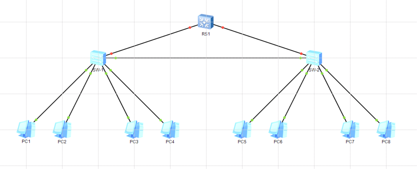
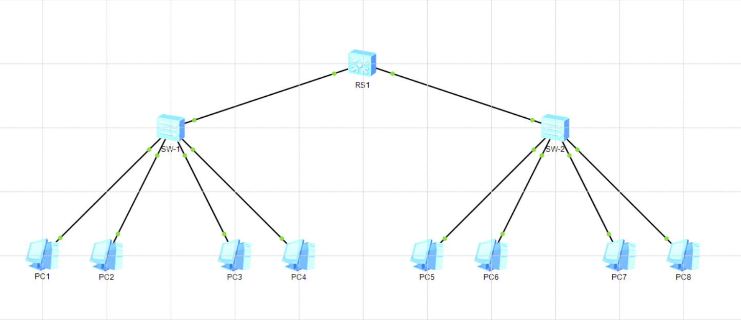
# 配置二层交换机端口
<SW-1>system-view
Enter system view, return user view with Ctrl+Z.
[SW-1]interface GigabitEthernet 0/0/2
[SW-1-GigabitEthernet0/0/2]port link-type trunk
[SW-1-GigabitEthernet0/0/2]port trunk allow-pass vlan 10 20
[SW-1-GigabitEthernet0/0/2]quit
[SW-1]quit
# 显示端口属性,
<SW-1>display port vlan
Port Link Type PVID Trunk VLAN List
-------------------------------------------------------------------------------
Ethernet0/0/1 access 10 -
Ethernet0/0/2 access 10 -

Ethernet0/0/5 access 20 -
Ethernet0/0/6 access 20 -

GigabitEthernet0/0/1 trunk 1 1 10 20
GigabitEthernet0/0/2 trunk 1 1 10 20

# 配置三层交换机
# 初始化
[Huawei]sysname RS-1
[RS-1]
[RS-1]interface GigabitEthernet0/0/1
[RS-1-GigabitEthernet0/0/1]undo negotiation auto
[RS-1-GigabitEthernet0/0/1]duplex full
[RS-1-GigabitEthernet0/0/1]speed 1000
[RS-1-GigabitEthernet0/0/1]flow-control
[RS-1-GigabitEthernet0/0/1]display this
#
interface GigabitEthernet0/0/1
undo negotiation auto
flow-control
#
return
[RS-1-GigabitEthernet0/0/1]description To_SW1
[RS-1-GigabitEthernet0/0/1]quit
[RS-1]
[RS-1]interface GigabitEthernet0/0/2
[RS-1-GigabitEthernet0/0/2]undo negotiation auto
[RS-1-GigabitEthernet0/0/2]duplex full
[RS-1-GigabitEthernet0/0/2]speed 1000
[RS-1-GigabitEthernet0/0/2]flow-control
[RS-1-GigabitEthernet0/0/2]display this
#
interface GigabitEthernet0/0/2
undo negotiation auto
flow-control
description To_SW2
#
return
[RS-1-GigabitEthernet0/0/2]description To_SW2
[RS-1-GigabitEthernet0/0/2]quit
# 创建VLAN
[RS-1]vlan batch 10 20
Info: This operation may take a few seconds. Please wait for a moment...done.
# 分配接口
[RS-1]interface GigabitEthernet 0/0/1
[RS-1-GigabitEthernet0/0/1]port link-type trunk
[RS-1-GigabitEthernet0/0/1]port trunk all
[RS-1-GigabitEthernet0/0/1]port trunk allow-pass vlan 10 20
[RS-1-GigabitEthernet0/0/1]quit
[RS-1]interface GigabitEthernet 0/0/2
[RS-1-GigabitEthernet0/0/2]port link-type trunk
[RS-1-GigabitEthernet0/0/2]port trunk allow-pass vlan 10 20
[RS-1-GigabitEthernet0/0/2]quit
# 显示VLAN
[RS-1]display vlan
The total number of vlans is : 3
--------------------------------------------------------------------------------
VID Status Property MAC-LRN Statistics Description
--------------------------------------------------------------------------------
1 enable default enable disable VLAN 0001
10 enable default enable disable VLAN 0010
20 enable default enable disable VLAN 0020
# 显示接口
[RS-1]display port vlan
Port Link Type PVID Trunk VLAN List
-------------------------------------------------------------------------------
GigabitEthernet0/0/1 trunk 1 1 10 20
GigabitEthernet0/0/2 trunk 1 1 10 20

# 配置三层路由
[RS-1]interface vlanif 10
[RS-1-Vlanif10]ip address 192.168.24.254 255.255.255.0
[RS-1-Vlanif10]quit
[RS-1]interface vlanif 20
[RS-1-Vlanif20]ip address 192.168.25.254 255.255.255.0
[RS-1-Vlanif20]quit

# 显示路由表
[RS-1]dis ip routing-table
Route Flags: R - relay, D - download to fib
------------------------------------------------------------------------------
Routing Tables: Public
Destinations : 6 Routes : 6

Destination/Mask Proto Pre Cost Flags NextHop Interface

127.0.0.0/8 Direct 0 0 D 127.0.0.1 InLoopBack0
127.0.0.1/32 Direct 0 0 D 127.0.0.1 InLoopBack0
192.168.24.0/24 Direct 0 0 D 192.168.24.254 Vlanif10
192.168.24.254/32 Direct 0 0 D 127.0.0.1 Vlanif10
192.168.25.0/24 Direct 0 0 D 192.168.25.254 Vlanif20
192.168.25.254/32 Direct 0 0 D 127.0.0.1 Vlanif20
# 主机测试

使用路由器

基础理论

路由器其实是一个逻辑概念,“有多个接口,用于连接多个IP子网及多种链路,能让它们互联互通的设备都可以被成为路由器”。路由器工作再OSI模型的第三层,也就是网络层。路由器通过逻辑的地址来划分区别不同的网络,从而实现网络之间的互联和隔离,并且路由器不转发广播消息,把广播消息限制再各自区域的网络中。路由器的核心是全局路由表。

路由有两个功能:路由决策和报文转发。

路由协议有三类:无需配置的链路层协议路由、静态路由和动态链路路由(RIP、OSPF、ISIS、BGP等)

路由器学习路由信息,生成并维护路由表的方式有三种:直连路由、静态路由和动态路由。

路由的选路原则有:最长匹配原则、路由优先级、路由开销

拓扑配置

二层交换机规划

序号 设备名称 接口 VLAN ID 对接设备/端口
1 SW-1 Ethernet 0/0/1 20 PC1
2 SW-1 Ethernet 0/0/2 21 PC2
3 SW-1 GE 0/0/1 1,21,22 RS-1
4 SW-2 Ethernet 0/0/1 23 PC3
5 SW-2 Ethernet 0/0/2 24 PC4
6 SW-2 GE 0/0/1 1,23,24 RS-2
7 SW-3 Ethernet 0/0/1 25 PC5
8 SW-3 Ethernet 0/0/2 26 PC6
9 SW-3 GE 0/0/0 1、25、26 RS-3
10 SW-4 Ethernet 0/0/1 27 PC-7
11 SW-4 Ethernet 0/0/2 28 PC-8
12 SW-4 GE 0/0/2 1、27、28 RS-4

三层交换机规划

序号 设备名称 接口 VLAN ID IP地址
1 RS-1 ge0/0/1 100 10.0.1.1
2 RS-1 ge0/024 20,21 192.168.20.254 192.168.21.254
3 RS-2 ge0/0/1 100 10.0.2.1
4 RS-2 ge0/0/24 22,23 192.168.22.254 192.168.23.254
5 RS-3 ge0/0/1 100 10.0.3.1
6 RS-3 ge0/0/24 24,25 192.168.24.254 192.168.25.254
7 RS-4 ge0/0/1 100 10.0.4.1
8 RS-4 ge0/0/24 26,27 192.168.26.254 192.168.27.254

路由器规划

序号 设备名称 接口 IP地址 掩码
1 R-1 ge0/0/0 10.0.0.1 32
2 R-1 ge0/0/1 10.0.1.2 32
3 R-1 ge0/0/2 10.0.2.2 32
4 R-2 ge0/0/0 10.0.0.2 32
5 R-2 ge0/0/1 10.0.0.5 32
6 R-3 ge0/0/0 10.0.0.6 32
7 R-3 ge0/0/1 10.0.3.2 32
8 R-3 ge0/0/2 10.0.4.2 32

主机IP地址规划表

序号 设备 IP地址/子网掩码 VLAN ID 接入交换机
1 PC1 192.168.20.1/24 20 SW-1 0/0/1
2 PC2 192.168.21.1/24 21 SW-1 0/0/2
3 PC3 192.168.22.1/24 22 SW-2 0/0/5
4 PC4 192.168.23.1/24 23 SW-2 0/0/6
5 PC5 192.168.24.1/24 24 SW-3 0/0/1
6 PC6 192.168.25.1/24 25 SW-3 0/0/2
7 PC7 192.168.26.1/24 26 SW-4 0/0/5
8 PC8 192.168.27.1/24 27 SW-4 0/0/6

配置二层交换机

1
2
3
4
5
6
7
8
9
10
11
12
13
14
15
16
17
18
19
20
21
22
23
24
25
26
27
28
29
30
31
32
33
34
35
36
37
38
39
40
41
42
43
44
45
46
# 交换机初始化
system-view
undo info-center enable
sysname SW-1

interface Ethernet0/0/1
undo negotiation auto
duplex full
speed 100
flow-control
display this
description To_PC1
quit

interface Ethernet0/0/2
undo negotiation auto
duplex full
speed 100
flow-control
display this
description To_PC2
quit

vlan batch 20 21

interface Eth0/0/1
port link-type access
port default vlan 20
quit

interface Eth0/0/2
port link-type access
port default vlan 21
quit


interface GigabitEthernet 0/0/1
port link-type trunk
port trunk allow-pass vlan 20 21
port link-type trunk
quit

display vlan
display port vlan
quit
save

配置三层交换机

1
2
3
4
5
6
7
8
9
10
11
12
13
14
15
16
17
18
19
20
21
22
23
24
25
26
27
28
29
30
31
32
33
34
35
# 使用vlanif接口实现vlan间通信
system-view
sysname RS-1
undo info-center enable
vlan batch 100 20 21

interface vlanif 20
ip addr 192.168.20.254 24
undo shutdown
quit

interface vlanif 21
ip addr 192.168.21.254 24
undo shutdown
quit

interface vlanif 100
ip addr 10.0.1.1 255.255.255.252
undo shutdown
quit

interface GigabitEthernet 0/0/1
port link-type access
port default vlan 100
quit

interface GigabitEthernet 0/0/24
port link-type trunk
port trunk allow-pass vlan 20 21
quit

ip route-static 0.0.0.0 0.0.0.0 10.0.1.2
quit
save
# 依次配置4台三层交换机

配置路由器

1
2
3
4
5
6
7
8
9
10
11
12
13
14
15
16
17
18
19
20
21
22
23
24
25
26
27
28
29
30
31
32
33
34
35
36
37
38
39
40
41
42
43
44
45
46
47
48
49
50
51
52
53
#配置第一台路由器
system-view
undo info-center enable
sysname R1

interface g0/0/0
ip address 10.0.0.1 255.255.255.252
undo shutdown
quit

interface g0/0/1
ip address 10.0.1.2 255.255.255.252
undo shutdown
quit

interface g0/0/2
ip address 10.0.2.2 255.255.255.252
undo shutdown
quit
# 配置第三台路由器
system-view
undo info-center enable
sysname R3

interface g0/0/0
ip address 10.0.0.6 255.255.255.252
undo shutdown
quit

interface g0/0/1
ip address 10.0.3.2 255.255.255.252
undo shutdown
quit

interface g0/0/2
ip address 10.0.4.2 255.255.255.252
undo shutdown
quit

# 配置二台路由器
system-view
undo info-center enable
sysname R2

interface g0/0/0
ip address 10.0.0.2 255.255.255.252
undo shutdown
quit

interface g0/0/1
ip address 10.0.0.5 255.255.255.252
undo shutdown
quit

使用静态路由

1
2
3
4
5
6
7
8
9
10
11
12
13
14
15
16
17
18
19
20
21
22
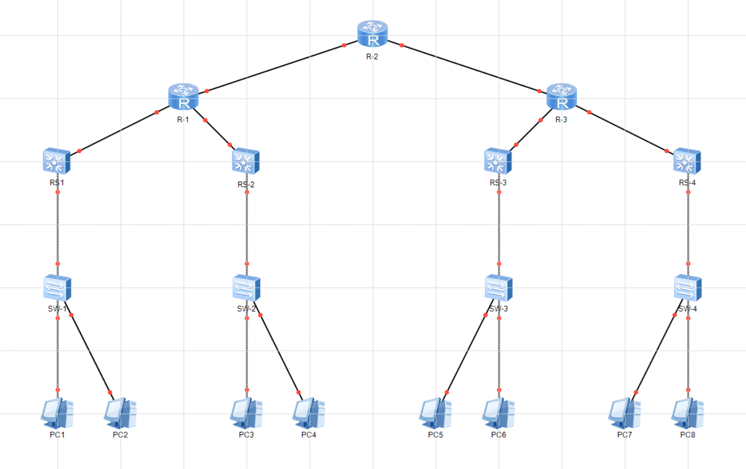
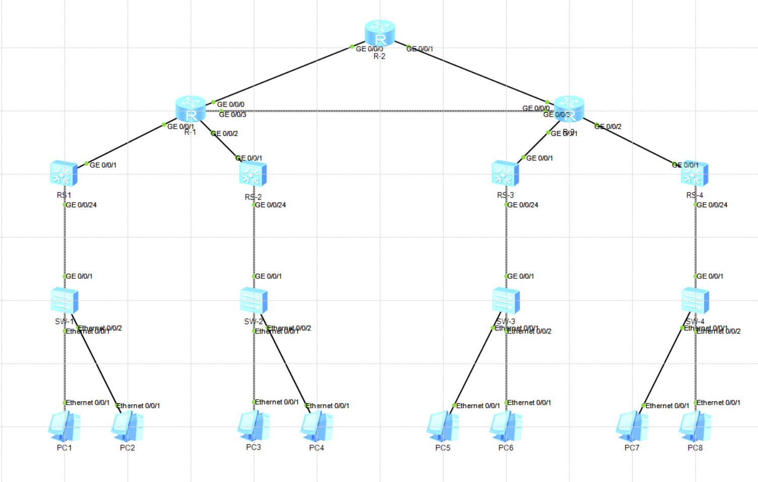
# 配置第一台路由
ip route-static 192.168.20.0 23 10.0.1.1
ip route-static 192.168.22.0 23 10.0.2.1
ip route-static 192.168.24.0 22 10.0.0.2
# 配置第三台路由
ip route-static 192.168.24.0 23 10.0.3.1
ip route-static 192.168.26.0 23 10.0.4.1
ip route-static 192.168.20.0 22 10.0.0.5
# 配置第二台路由
ip route-static 192.168.24.0 22 10.0.0.6
ip route-static 192.168.20.0 22 10.0.0.1

# 从PC1上查看路由经过
PC>tracert 192.168.27.1
traceroute to 192.168.27.1, 8 hops max
(ICMP), press Ctrl+C to stop
1 192.168.20.254 47 ms 47 ms 47 ms
2 10.0.1.2 78 ms 62 ms 78 ms
3 10.0.0.2 110 ms 78 ms 125 ms
4 10.0.0.6 109 ms 125 ms 125 ms
5 10.0.4.1 156 ms 141 ms 156 ms
6 192.168.27.1 219 ms 156 ms 157 ms
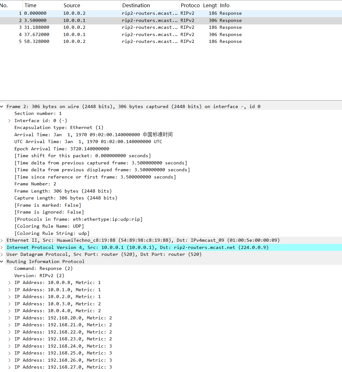
使用RIP

认识RIP

RIP(Routing Information Protocol)路由信息协议,是一种基于距离矢量算法的协议,它使用跳数(HopCount)作为度量衡值来衡量到达目的地址的距离。

在RIP网络中,缺省情况下,设备到于它直接相连通的网络跳数为0,通过一个设备可达的网络的跳数为1,其余依次类推。

度量值等于从本网络到达目的网络间的设备数量。RIP通过UDP报文进行路由信息的交换,使用端口为520。

RIP的特点

  1. 仅和相邻路由器交换信息
  2. 路由器之间交换的路由信息是当前本路由器中的完整路由表
  3. 按固定时间间隔交换路由信息

RIP实验

  1. 拓扑如上,沿用上一次静态路由实验配置

  2. 配置RIP

    1
    2
    3
    4
    5
    6
    7
    8
    9
    10
    11
    12
    13
    14
    15
    16
    17
    18
    19
    20
    21
    22
    23
    24
    25
    26
    27
    28
    29
    30
    31
    32
    33
    34
    35
    36
    37
    38
    39
    40
    41
    42
    43
    44
    45
    46
    47
    48
    49
    50
    51
    52
    53
    54
    55
    56
    57
    58
    59
    60
    61
    62
    63
    64
    65
    66
    67
    68
    69
    70
    71
    72
    73
    74
    75
    76
    77
    78
    79
    80
    81
    82
    83
    84
    85
    86
    87
    88
    89
    90
    91
    92
    93
    94
    95
    96
    97
    98
    99
    100
    101
    # 配置三层交换机
    [RS-1]rip 1
    [RS-1-rip-1]vers
    [RS-1-rip-1]version 2
    [RS-1-rip-1]netw
    [RS-1-rip-1]network 192.168.20.0
    [RS-1-rip-1]netwo
    [RS-1-rip-1]network 192.168.21.0
    [RS-1-rip-1]network 10.0.0.0
    [RS-1-rip-1]quit
    # 依次配置路由器
    [R1]rip 1
    [R1-rip-1]versio
    [R1-rip-1]version 2
    [R1-rip-1]net
    [R1-rip-1]netwo
    [R1-rip-1]network 10.0.0.0
    # 查看RS-1路由表,RS-1获取RS-4的网络信息
    [RS-1]dis ip routing-table
    Route Flags: R - relay, D - download to fib
    ------------------------------------------------------------------------------
    Routing Tables: Public
    Destinations : 20 Routes : 20

    Destination/Mask Proto Pre Cost Flags NextHop Interface

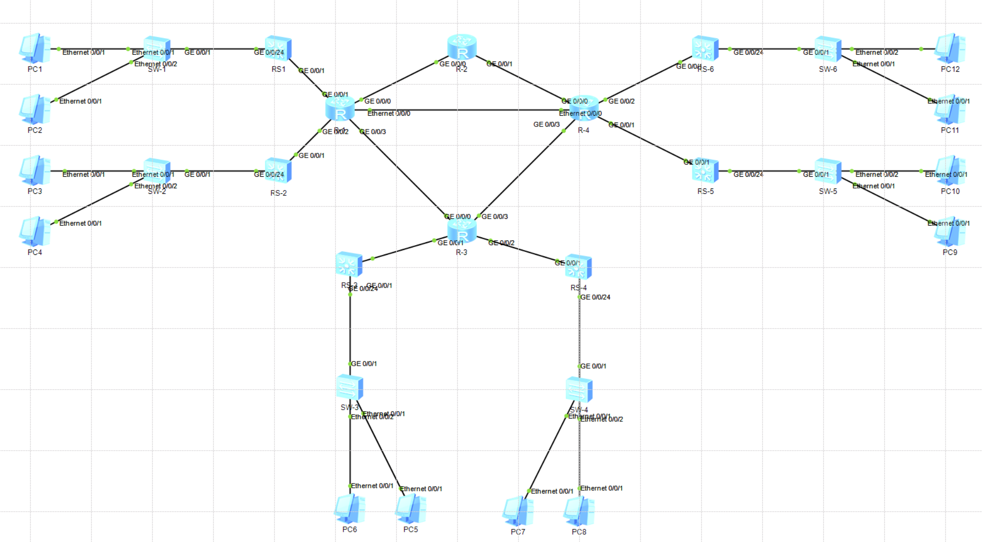
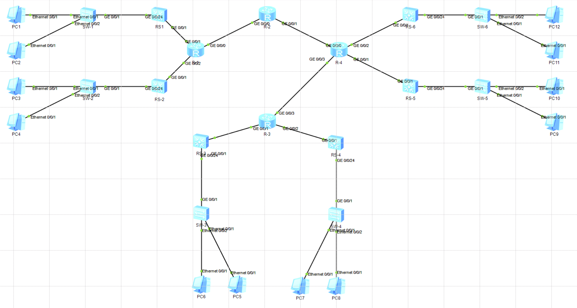
    10.0.0.0/30 RIP 100 1 D 10.0.1.2 Vlanif100
    10.0.0.4/30 RIP 100 2 D 10.0.1.2 Vlanif100
    10.0.0.8/30 RIP 100 1 D 10.0.1.2 Vlanif100
    10.0.1.0/30 Direct 0 0 D 10.0.1.1 Vlanif100
    10.0.1.1/32 Direct 0 0 D 127.0.0.1 Vlanif100
    10.0.2.0/30 RIP 100 1 D 10.0.1.2 Vlanif100
    10.0.3.0/30 RIP 100 2 D 10.0.1.2 Vlanif100
    10.0.4.0/30 RIP 100 2 D 10.0.1.2 Vlanif100
    127.0.0.0/8 Direct 0 0 D 127.0.0.1 InLoopBack0
    127.0.0.1/32 Direct 0 0 D 127.0.0.1 InLoopBack0
    192.168.20.0/24 Direct 0 0 D 192.168.20.254 Vlanif20
    192.168.20.254/32 Direct 0 0 D 127.0.0.1 Vlanif20
    192.168.21.0/24 Direct 0 0 D 192.168.21.254 Vlanif21
    192.168.21.254/32 Direct 0 0 D 127.0.0.1 Vlanif21
    192.168.22.0/24 RIP 100 2 D 10.0.1.2 Vlanif100
    192.168.23.0/24 RIP 100 2 D 10.0.1.2 Vlanif100
    192.168.24.0/24 RIP 100 3 D 10.0.1.2 Vlanif100
    192.168.25.0/24 RIP 100 3 D 10.0.1.2 Vlanif100
    192.168.26.0/24 RIP 100 3 D 10.0.1.2 Vlanif100
    192.168.27.0/24 RIP 100 3 D 10.0.1.2 Vlanif100
    # 查看R-2路由器的路由表,可以看到大量通过RIP获取的路由信息
    [R2]dis ip routing-table
    Route Flags: R - relay, D - download to fib
    ------------------------------------------------------------------------------
    Routing Tables: Public
    Destinations : 19 Routes : 20

    Destination/Mask Proto Pre Cost Flags NextHop Interface

    10.0.0.0/30 Direct 0 0 D 10.0.0.2 GigabitEthernet0/0/0
    10.0.0.2/32 Direct 0 0 D 127.0.0.1 GigabitEthernet0/0/0
    10.0.0.4/30 Direct 0 0 D 10.0.0.5 GigabitEthernet0/0/1
    10.0.0.5/32 Direct 0 0 D 127.0.0.1 GigabitEthernet0/0/1
    10.0.0.8/30 RIP 100 1 D 10.0.0.1 GigabitEthernet0/0/0
    RIP 100 1 D 10.0.0.6 GigabitEthernet0/0/1
    10.0.1.0/30 RIP 100 1 D 10.0.0.1 GigabitEthernet0/0/0
    10.0.2.0/30 RIP 100 1 D 10.0.0.1 GigabitEthernet0/0/0
    10.0.3.0/30 RIP 100 1 D 10.0.0.6 GigabitEthernet0/0/1
    10.0.4.0/30 RIP 100 1 D 10.0.0.6 GigabitEthernet0/0/1
    127.0.0.0/8 Direct 0 0 D 127.0.0.1 InLoopBack0
    127.0.0.1/32 Direct 0 0 D 127.0.0.1 InLoopBack0
    192.168.20.0/24 RIP 100 2 D 10.0.0.1 GigabitEthernet0/0/0
    192.168.21.0/24 RIP 100 2 D 10.0.0.1 GigabitEthernet0/0/0
    192.168.22.0/24 RIP 100 2 D 10.0.0.1 GigabitEthernet0/0/0
    192.168.23.0/24 RIP 100 2 D 10.0.0.1 GigabitEthernet0/0/0
    192.168.24.0/24 RIP 100 2 D 10.0.0.6 GigabitEthernet0/0/1
    192.168.25.0/24 RIP 100 2 D 10.0.0.6 GigabitEthernet0/0/1
    192.168.26.0/24 RIP 100 2 D 10.0.0.6 GigabitEthernet0/0/1
    192.168.27.0/24 RIP 100 2 D 10.0.0.6 GigabitEthernet0/0/1

    # 验证结果
    PC>traceroute 192.168.27.1
    Invalid command!

    PC>tracert 192.168.27.1

    traceroute to 192.168.27.1, 8 hops max
    (ICMP), press Ctrl+C to stop
    1 192.168.20.254 47 ms 47 ms 46 ms
    2 10.0.1.2 110 ms 62 ms 94 ms
    3 10.0.0.10 141 ms 109 ms 109 ms
    4 10.0.4.1 719 ms 110 ms 140 ms
    5 192.168.27.1 219 ms 203 ms 203 ms
    # 相比静态路由减少一跳
    # 断开10.0.0.9到10.0.0.10之间的链路,可以发现路由动态修改
    PC>tracert 192.168.27.1

    traceroute to 192.168.27.1, 8 hops max
    (ICMP), press Ctrl+C to stop
    1 192.168.20.254 63 ms 47 ms 47 ms
    2 10.0.1.2 62 ms 63 ms 47 ms
    3 10.0.0.2 125 ms 93 ms 94 ms
    4 10.0.0.6 172 ms 109 ms 110 ms
    5 10.0.4.1 125 ms 156 ms 172 ms
    6 *192.168.27.1 204 ms 187 ms

OSPF的应用

什么是OSPF

RIP是基于距离矢量算法的路由协议,存在着收敛慢、路由环路、可扩展性差等问题,被OSPF协议所取代。OSPF是IEEE开发的基于链路状态的内部网关协议,是目前网络中应用最广泛的路由协议之一。

OSPF通过泛洪向整个自治系统中的所有路由器发送信息,扩散本设备的链路状态信息,使得网络中的每台路由器最终都能建立一个全网链路状态数据库LSDB,LSDB实际就是全网的拓扑结构图。每个路由器都使用链路状态数据库中的数据,采用最短路径算法,通过链路状态通告LSA描述网络拓扑,并以自己为根,生成最短路径树SPT,计算到达其他网络的最短路径,构造出自己的路由表,最终形成全网路由信息。

OSPF属于无类路由协议,支持可变长子网掩码VLSM。

OSPF直接使用IP数据报传送,其IP数据报首部的协议字段值为89.

OSPF共有以下5组分组类型

  1. 问候,Hello分组,用来发现和维持邻站的可达性
  2. 数据库描述,DD分组,向邻站给出自己的链路状态数据库中所有链路状态项目的摘要信息
  3. 链路状态请求,LSR分组,向对方请求发送某些链路状态项目的详细信息
  4. 链路状态更新,LSU分组,用泛洪法对全网更新链路状态
  5. 链路状态确认,LSAck分组,对链路更新的确认

OSPF的区域

通过划分区域将链路状态信息局限在每一个区域而不是整个自治系统。每个区域用32位ID标识区域。

OSPF特点

  1. 适应范围广
  2. 快速收敛
  3. 支持掩码
  4. 区域划分
  5. 等价路由
  6. 支持验证

组网实验

环境准备

延用前述实验拓扑,新增一个R-4路由的区域

序号 设备名称 接口 IP地址 连接
1 R-1 ge0/0/0 10.0.0.1 R-1
2 R-1 ge0/0/1 10.0.1.2 RS-1
3 R-1 ge0/0/2 10.0.2.2 RS-2
4 R-1 ge0/0/3 10.0.0.14 R-3
5 R-1 e0/0/0 10.0.0.17 R-4
6 R-2 ge0/0/0 10.0.0.2 R-1
7 R-2 ge0/0/1 10.0.0.5 R-4
8 R-3 ge0/0/0 10.0.0.13 R-1
9 R-3 ge0/0/1 10.0.3.2 RS-3
10 R-3 ge0/0/2 10.0.4.2 RS-4
11 R-3 ge0/0/3 10.0.0.10 R-4
12 R-4 ge0/0/0 10.0.0.6 R-1
13 R-4 ge0/0/1 10.0.5.2 RS-5
14 R-4 ge0/0/2 10.0.6.2 RS-6
15 R-4 ge0/0/3 10.0.0.9 R-3
16 R-4 e0/0/0 10.0.0.18 R-2
二层交换机的准备
1
2
3
4
5
6
7
8
9
10
11
12
13
14
15
16
17
18
19
20
21
22
23
24
25
26
27
28
29
30
31
32
33
34
35
36
37
38
39
40
41
42
43
44
45
46
system-view
undo info-center enable
sysname SW-5

interface Ethernet0/0/1
undo negotiation auto
duplex full
speed 100
flow-control
display this
description To_PC09
quit

interface Ethernet0/0/2
undo negotiation auto
duplex full
speed 100
flow-control
display this
description To_PC10
quit

vlan batch 28 29

interface Eth0/0/1
port link-type access
port default vlan 28
quit

interface Eth0/0/2
port link-type access
port default vlan 29
quit

interface GigabitEthernet 0/0/1
duplex full
speed 1000
port link-type trunk
port trunk allow-pass vlan 28 29
port link-type trunk
quit

display vlan
display port vlan
quit
save
三层交换机的准备
1
2
3
4
5
6
7
8
9
10
11
12
13
14
15
16
17
18
19
20
21
22
23
24
25
26
27
28
29
30
31
system-view
sysname RS-5
undo info-center enable
vlan batch 100 28 29

interface vlanif 28
ip addr 192.168.28.254 24
undo shutdown
quit

interface vlanif 29
ip addr 192.168.29.254 24
undo shutdown
quit

interface vlanif 100
ip addr 10.0.5.1 255.255.255.252
undo shutdown
quit

interface GigabitEthernet 0/0/1
port link-type access
port default vlan 100
quit

interface GigabitEthernet 0/0/24
port link-type trunk
port trunk allow-pass vlan 28 29
quit
quit
save

OSPF配置

三层交换机配置
1
2
3
4
5
6
7
8
9
10
11
12
13
14
15
16
17
18
19
20
21
22
23
24
25
26
27
28
# RS-1
system-view
ospf 1
area 1
network 192.168.20.0 0.0.0.255
network 192.168.21.0 0.0.0.255
network 10.0.1.0 0.0.0.3
quit
quit
# RS-3
system-view
ospf 1
area 2
network 192.168.24.0 0.0.0.255
network 192.168.25.0 0.0.0.255
network 10.0.3.0 0.0.0.3
quit
quit
# RS-5
system-view
ospf 1
area 3
network 192.168.28.0 0.0.0.255
network 192.168.29.0 0.0.0.255
network 10.0.5.0 0.0.0.3
quit
quit
# 以此类推完成RS-2到RS-6

路由器配置

1
2
3
4
5
6
7
8
9
10
11
12
13
14
15
16
17
18
19
20
21
22
23
24
25
26
27
28
29
30
31
32
33
34
35
36
37
38
39
40
41
42
43
44
45
46
47
48
49
50
51
52
53
54
55
56
57
58
59
60
61
62
63
64
65
66
67
68
69
70
71
72
73
74
75
76
77
78
79
80
81
82
83
84
85
86
87
88
89
90
91
92
93
94
95
96
97
98
99
100
101
102
103
104
105
106
107
108
109
110
111
112
113
114
115
116
117
118
119
120
121
122
123
124
125
126
127
128
129
130
131
132
133
134
135
136
137
138
139
140
141
142
143
144
145
146
147
148
149
150
151
152
153
154
155
156
157
158
159
160
161
162
163
164
165
166
167
168
169
170
171
172
173
174
175
176
177
178
179
180
181
182
183
184
185
186
187
188
189
190
# R-1
system-view
undo info-center enable
sysname R1

interface g0/0/0
ip address 10.0.0.1 255.255.255.252
undo shutdown
display this
quit

interface g0/0/1
ip address 10.0.1.2 255.255.255.252
undo shutdown
display this
quit

interface g0/0/2
ip address 10.0.2.2 255.255.255.252
undo shutdown
display this
quit

interface g0/0/3
ip address 10.0.0.14 255.255.255.252
undo shutdown
display this
quit

interface eth0/0/0
ip address 10.0.0.17 255.255.255.252
undo shutdown
display this
quit

ospf 1
area 0
network 10.0.0.0 0.0.0.3
network 10.0.0.12 0.0.0.3
network 10.0.0.16 0.0.0.3
quit

area 1
network 10.0.1.0 0.0.0.3
network 10.0.2.0 0.0.0.3
quit
quit

# R-2
system-view
undo info-center enable
sysname R2

interface g0/0/0
ip address 10.0.0.2 255.255.255.252
undo shutdown
quit

interface g0/0/1
ip address 10.0.0.5 255.255.255.252
undo shutdown
quit

ospf 1
area 0
network 10.0.0.0 0.0.0.3
network 10.0.0.4 0.0.0.3
quit
quit

# R-3
system-view
undo info-center enable
sysname R3

interface g0/0/0
ip address 10.0.0.13 255.255.255.252
undo shutdown
display this
quit

interface g0/0/1
ip address 10.0.3.2 255.255.255.252
undo shutdown
display this
quit

interface g0/0/2
ip address 10.0.4.2 255.255.255.252
undo shutdown
display this
quit

interface g0/0/3
ip address 10.0.0.10 255.255.255.252
undo shutdown
display this
quit


ospf 1
area 0
network 10.0.0.12 0.0.0.3
network 10.0.0.8 0.0.0.3
quit

area 2
network 10.0.3.0 0.0.0.3
network 10.0.4.0 0.0.0.3
quit
quit

# R-4
system-view
undo info-center enable
sysname R4

interface g0/0/0
ip address 10.0.0.6 255.255.255.252
undo shutdown
display this
quit

interface g0/0/1
ip address 10.0.5.2 255.255.255.252
undo shutdown
display this
quit

interface g0/0/2
ip address 10.0.6.2 255.255.255.252
undo shutdown
display this
quit

interface g0/0/3
ip address 10.0.0.9 255.255.255.252
undo shutdown
display this
quit

interface eth0/0/0
ip address 10.0.0.18 255.255.255.252
undo shutdown
display this
quit

ospf 1
area 0
network 10.0.0.4 0.0.0.3
network 10.0.0.8 0.0.0.3
network 10.0.0.16 0.0.0.3
quit

area 3
network 10.0.5.0 0.0.0.3
network 10.0.6.0 0.0.0.3
quit
quit

# 检查ospf获取信息
[R2]dis ip routing-table
Route Flags: R - relay, D - download to fib
------------------------------------------------------------------------------
Routing Tables: Public
Destinations : 20 Routes : 20

Destination/Mask Proto Pre Cost Flags NextHop Interface

10.0.0.0/30 Direct 0 0 D 10.0.0.2 GigabitEthernet0/0/0
10.0.0.2/32 Direct 0 0 D 127.0.0.1 GigabitEthernet0/0/0
10.0.0.4/30 Direct 0 0 D 10.0.0.5 GigabitEthernet0/0/1
10.0.0.5/32 Direct 0 0 D 127.0.0.1 GigabitEthernet0/0/1
10.0.0.8/30 OSPF 10 2 D 10.0.0.6 GigabitEthernet0/0/1
10.0.0.16/30 OSPF 10 2 D 10.0.0.6 GigabitEthernet0/0/1
10.0.1.0/30 OSPF 10 2 D 10.0.0.1 GigabitEthernet0/0/0
10.0.2.0/30 OSPF 10 2 D 10.0.0.1 GigabitEthernet0/0/0
10.0.5.0/30 OSPF 10 2 D 10.0.0.6 GigabitEthernet0/0/1
10.0.6.0/30 OSPF 10 2 D 10.0.0.6 GigabitEthernet0/0/1
127.0.0.0/8 Direct 0 0 D 127.0.0.1 InLoopBack0
127.0.0.1/32 Direct 0 0 D 127.0.0.1 InLoopBack0
192.168.20.0/24 OSPF 10 3 D 10.0.0.1 GigabitEthernet0/0/0
192.168.21.0/24 OSPF 10 3 D 10.0.0.1 GigabitEthernet0/0/0
192.168.22.0/24 OSPF 10 3 D 10.0.0.1 GigabitEthernet0/0/0
192.168.23.0/24 OSPF 10 3 D 10.0.0.1 GigabitEthernet0/0/0
192.168.28.0/24 OSPF 10 3 D 10.0.0.6 GigabitEthernet0/0/1
192.168.29.0/24 OSPF 10 3 D 10.0.0.6 GigabitEthernet0/0/1
192.168.30.0/24 OSPF 10 3 D 10.0.0.6 GigabitEthernet0/0/1
192.168.31.0/24 OSPF 10 3 D 10.0.0.6 GigabitEthernet0/0/1

验证

1
2
3
4
5
6
7
8
9
10
# 使用PC1进行路由跟踪,可见数据包经过了RS-1、R1、R3、RS-4抵达PC8
PC>tracert 192.168.27.1

traceroute to 192.168.27.1, 8 hops max
(ICMP), press Ctrl+C to stop
1 192.168.20.254 47 ms 63 ms 47 ms
2 10.0.1.2 78 ms 78 ms 78 ms
3 10.0.0.13 94 ms 109 ms 94 ms
4 10.0.4.1 125 ms 109 ms 110 ms
5 *192.168.27.1 156 ms 141 ms

1
2
3
4
5
6
7
8
9
10
11
12
# 中断中间线路之后,路由发生变化,可见数据包经过了RS-1、R1、R2、R4、R3、RS-4抵达PC8
PC>tracert 192.168.27.1

traceroute to 192.168.27.1, 8 hops max
(ICMP), press Ctrl+C to stop
1 192.168.20.254 47 ms 46 ms 32 ms
2 10.0.1.2 78 ms 62 ms 63 ms
3 10.0.0.2 78 ms 94 ms 78 ms
4 10.0.0.6 109 ms 125 ms 110 ms
5 10.0.0.10 125 ms 140 ms 125 ms
6 10.0.4.1 156 ms 157 ms 156 ms
7 *192.168.27.1 203 ms 219 ms